Msc2G7:Joint preparation
Joint preparation
PREPARATION INDIVIDUAL PARTS
1. The 3D printed structure
Print the 3 parts of the joint. Remove support structure
Refine the holes with 8mm and 5mm drills.
2. Axles
Per joint 2 axles need to be made; one 36mm(upper) and the other 52mm(lower).
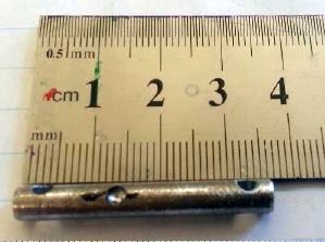
2.a The upper axle (36mm)
Holes: 3mm drill. Two holes 4mm from each side.
45degree w.r.t. the holes.
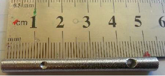
2.b The lower axle (52mm)
Hole: 3mm drill. One hole 9mm from the right side.
Gap: One little gap at 14mm from the left side.
Sand both axles down so that they fit through the 5mm bearing.
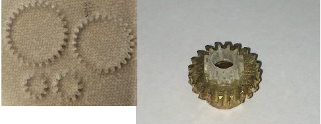
3. Gears
Laser cut the gear file onto 3mm perplex. (Epilog settings at workshop: ‘print selection’ “vector, speed 50, power 67, frequency 5000”)
Print the (red) inside of the gears first. Remove from sheet.
Glue the two little gears to the flat side of the messing (worm drive) gear
4. Servo modification
Be careful. Unscrew the four black inbus/hex screws. Take off the top cap with the gears.
Unscrew the two little Philips screws. Take off silver ring of the case. There is one screw under the circuit board to be taken out as well. The motor and the potentiometer (later referred to as potmeter) are now lose.
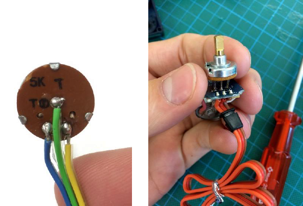
5. Soldering
Cut the three pins as close to the potmeter as possible. Solder the wires as in the picture. Watch the oretation though; the upper servo connected as it was on the board(A-1,B-2,C-3) and for the down servo it is wired exactly opposite (A-3,B-2,C-1).
6. Worm gear
Cut the little 2-4mm tube to 20mm. Put the tube in the worm gear. Put the bolt through the tube. Screw it onto the servo.
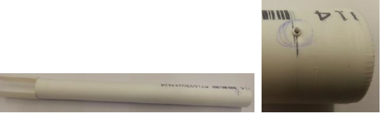
7. Tube
Cut the tube at 30 cm, sand down both ends to put in the griper and connecting piece. Drill a 2.5mm hole at the connecting piece end.