Difference between revisions of "Msc2G7:Expert1"
(→Prototype 2) |
Gary Chang (Talk | contribs) |
||
| (38 intermediate revisions by 4 users not shown) | |||
| Line 1: | Line 1: | ||
__NOTOC__ __NOTITLE__ | __NOTOC__ __NOTITLE__ | ||
| − | ==Joints&Calculations== | + | |
| + | ==Joints & Calculations== | ||
<div style="height:30px; width: 850px; margin:0px; padding: 0px; padding-top: 20px; border: 0px;"> | <div style="height:30px; width: 850px; margin:0px; padding: 0px; padding-top: 20px; border: 0px;"> | ||
| − | <div style="float:left; width: | + | <div style="float:left; width: 90px; height 30px; border: 1px solid #aaa; margin-right:8px; " align="center"> |
| − | [[Msc2G7:Frontpage|'''BOP''']] | + | [[Msc2G7:Frontpage|''' BOP ''']] |
| + | </div> | ||
| + | <div style="float:left; width: 120px; height 30px; border: 1px solid #aaa; margin-right:8px" align="center"> | ||
| + | [[Msc2G7:Expert5|''' Weekly Planning ''']] | ||
</div> | </div> | ||
<div style="float:left; width: 130px; height 30px; border: 1px solid #aaa; margin-right:8px; " align="center"> | <div style="float:left; width: 130px; height 30px; border: 1px solid #aaa; margin-right:8px; " align="center"> | ||
| − | [[Msc2G7:Expert1|'''Joints&Calculations''']] | + | [[Msc2G7:Expert1|''' Joints&Calculations ''']] |
</div> | </div> | ||
| − | <div style="float:left; width: | + | <div style="float:left; width: 120px; height 30px; border: 1px solid #aaa; margin-right:8px;" align="center"> |
| − | [[Msc2G7:Expert3|'''Motors&Sensors''']] | + | [[Msc2G7:Expert3|''' Motors&Sensors ''']] |
</div> | </div> | ||
| − | <div style="float:left; width: | + | <div style="float:left; width: 90px; height 30px; border: 1px solid #aaa; margin-right:8px" align="center"> |
| − | [[Msc2G7:Expert4|'''Control''']] | + | [[Msc2G7:Expert4|''' Control ''']] |
</div> | </div> | ||
<div style="float:left; width: 130px; height 30px; border: 1px solid #aaa; margin-right:8px" align="center"> | <div style="float:left; width: 130px; height 30px; border: 1px solid #aaa; margin-right:8px" align="center"> | ||
| − | [[Msc2G7: | + | [[Msc2G7:Expert6|''' Plenary Session 2 ''']] |
</div> | </div> | ||
| − | <div style="float:left; width: | + | <div style="float:left; width: 90px; height 30px; border: 1px solid #aaa;" align="center"> |
| − | [[Msc2G7: | + | [[Msc2G7:Questions|''' Questions ''']] |
</div> | </div> | ||
</div><br> | </div><br> | ||
| + | == Photos prototype 2 == | ||
| + | [[File:IMG 3050.JPG|200px]] | ||
| + | [[File:IMG 3049.JPG|200px]] | ||
| + | [[File:IMG 3048.JPG|200px]] | ||
| + | [[File:IMG 3047.JPG|300px]] | ||
| + | [[File:IMG 3046.JPG|200px]] | ||
| + | [[File:IMG 3045.JPG|200px]] | ||
| + | [[File:IMG 3044.jpg|200px]] | ||
| + | [[File:IMG 3043.jpg|200px]] | ||
| + | [[File:IMG 3042.jpg|200px]] | ||
| + | [[File:IMG 3041.jpg|200px]] | ||
| + | [[File:IMG 3040.jpg|200px]] | ||
| + | [[File:IMG 3039.jpg|200px]] | ||
| + | [[File:IMG 3038.jpg|200px]] | ||
| + | [[File:IMG 3037.jpg|200px]] | ||
| + | [[File:IMG 3036.jpg|200px]] | ||
| + | [[File:IMG 3035.jpg|200px]] | ||
| − | == | + | == 25/3 Evaluation of prototype 1 == |
| − | + | <br/> | |
| + | The first prototype has brought some insights in this design. To keep improving the design for the best end result we will make some adjustments for the second prototype according to the following points of attention. | ||
| + | <br/><br/> | ||
| − | [[File:Prototype_2.jpg| | + | <u>Advantages</u> <br/> |
| + | *The round shape is good for wear and friction with the ground.<br/> | ||
| + | *And it hands good opportunities to make it water tight. round | ||
| + | *The shell protects the motors from hitting the ground. <br/> | ||
| + | |||
| + | <br/><br/> | ||
| + | <u>Points of improvement</u><br/> | ||
| + | *Hard to maintain or to replace elements because of the big closed case.<br/> | ||
| + | *This perfect roundness is a very bad shape for scaling up for the eventual pavilion. <br/> | ||
| + | *And it makes the joint big and that is bad for the shape perception. <br/> | ||
| + | *The bearings in this prototype are big and heavy.<br/> | ||
| + | |||
| + | == 23/3 Estimation joint weight/cost Prototype 2 == | ||
| + | {| class="wikitable" | ||
| + | |- style="vertical-align:middle;" | ||
| + | | style="height:20px; width:400px;" | '''Name''' | ||
| + | | style="height:20px; width:220px;" | '''Weight (gram)''' | ||
| + | | style="height:20px; width:220px;" | '''Costs (€)''' | ||
| + | |- style="vertical-align:top;" | ||
| + | | style="height:25px;" | Servo (2x) (BMS-621DMG) | ||
| + | | style="height:25px;" | 2 x 50 | ||
| + | | style="height:25px;" | 2 x 25 | ||
| + | |- style="vertical-align:top;" | ||
| + | | style="height:25px;" | Computer (arduino) | ||
| + | | style="height:25px;" | 30 | ||
| + | | style="height:25px;" | 20 | ||
| + | |- style="vertical-align:top;" | ||
| + | | style="height:25px;" | Stucture | ||
| + | | style="height:25px;" | 50 (estimate) | ||
| + | | style="height:25px;" | N.A. | ||
| + | |- style="vertical-align:top;" | ||
| + | | style="height:25px;" | Proximity sensor (2x) | ||
| + | | style="height:25px;" | 2 x 10 | ||
| + | | style="height:25px;" | N.A. | ||
| + | |- style="vertical-align:top;" | ||
| + | | style="height:25px;" | Plain bearing (2-4x) | ||
| + | | style="height:25px;" | 2 x 20 | ||
| + | | style="height:25px;" | ??? | ||
| + | |- style="vertical-align:top;" | ||
| + | | style="height:25px;" | Worm Gearbox (2x) | ||
| + | | style="height:25px;" | 2 x 20 | ||
| + | | style="height:25px;" | 2 x 13 | ||
| + | |- style="vertical-align:top;" | ||
| + | | style="height:25px;" | Tube | ||
| + | | style="height:25px;" | N.A. | ||
| + | | style="height:25px;" | 5 | ||
| + | |- style="vertical-align:top;" | ||
| + | | style="height:25px;" | '''Total''' | ||
| + | | style="height:25px;" | '''280''' | ||
| + | | style="height:25px;" | '''101''' | ||
| + | |} | ||
| + | For our second prototype and probably our final design we are not going to use batteries. The tube is not part of the weight of the joint. We overdimensioned the total weight to '''350 gram''' for unexpected setbacks. | ||
| + | |||
| + | == 16/3 Prototype 2 == | ||
| + | First drawings of the second prototype. The second prototype is focused on creating a joint that makes the structure better resembles a loop and has a integrated gearbox. | ||
| + | |||
| + | [[File:Prototype_2.jpg|840px]] | ||
== 16/3 Prototype 1 (for testing) == | == 16/3 Prototype 1 (for testing) == | ||
We designed a joint to test the calcultations made. Here are some pictures of the process of 3D printing the joint. | We designed a joint to test the calcultations made. Here are some pictures of the process of 3D printing the joint. | ||
| − | [[File:Prototype_1.1.jpg| | + | [[File:Prototype_1.1.jpg|168px]][[File:Prototype_1.2.jpg|168px]][[File:Prototype_1.3.jpg|168px]][[File:Prototype_1.4.jpg|168px]] |
| − | + | <br/>[[File:Prototype_1.6.jpg|400px]] | |
== 10/3 Calculations == | == 10/3 Calculations == | ||
Before designing the joint calculation had to be made to get a idea of the forces working on the structure. The following link will lead to the calculations made in Matlab. | Before designing the joint calculation had to be made to get a idea of the forces working on the structure. The following link will lead to the calculations made in Matlab. | ||
| − | + | (link deleted) | |
The Zip file costains 5 files: | The Zip file costains 5 files: | ||
| Line 74: | Line 153: | ||
---- | ---- | ||
[[File:SJ_01.jpg| 210px]][[File:SJ_03.jpg| 210px]][[File:SJ_06.jpg| 210px]][[File:SJ_07.jpg| 210px]] | [[File:SJ_01.jpg| 210px]][[File:SJ_03.jpg| 210px]][[File:SJ_06.jpg| 210px]][[File:SJ_07.jpg| 210px]] | ||
| + | |||
[[File:SJ_11.jpg| 280px]][[File:SJ_08.jpg| 280px]][[File:SJ_05.jpg| 280px]] | [[File:SJ_11.jpg| 280px]][[File:SJ_08.jpg| 280px]][[File:SJ_05.jpg| 280px]] | ||
| + | |||
| + | [[File:AnaLoop_02.jpg| 420px]][[File:AnaLoop_03.jpg| 420px]] | ||
== 2/3 Decisions Joint Prototype 1 == | == 2/3 Decisions Joint Prototype 1 == | ||
| Line 100: | Line 182: | ||
[[Image:Joint_2.JPG| 400px]][[Image:Loop.JPG| 400px]] | [[Image:Joint_2.JPG| 400px]][[Image:Loop.JPG| 400px]] | ||
| + | |||
| + | ---- | ||
| + | With the support of the Culture Programme of the EU.<br> | ||
| + | [[File:EU_flag.jpg|420px]][[File:META_logo.jpg|420px]] | ||
Latest revision as of 10:47, 23 March 2016
Joints & Calculations
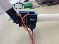
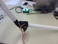
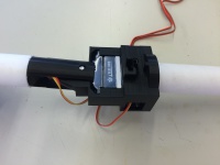
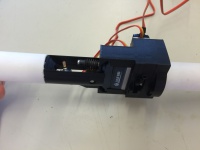
Photos prototype 2
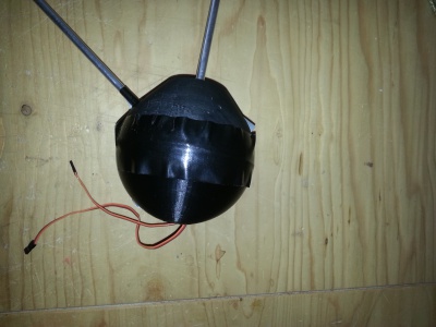
25/3 Evaluation of prototype 1
The first prototype has brought some insights in this design. To keep improving the design for the best end result we will make some adjustments for the second prototype according to the following points of attention.
Advantages
- The round shape is good for wear and friction with the ground.
- And it hands good opportunities to make it water tight. round
- The shell protects the motors from hitting the ground.
Points of improvement
- Hard to maintain or to replace elements because of the big closed case.
- This perfect roundness is a very bad shape for scaling up for the eventual pavilion.
- And it makes the joint big and that is bad for the shape perception.
- The bearings in this prototype are big and heavy.
23/3 Estimation joint weight/cost Prototype 2
| Name | Weight (gram) | Costs (€) |
| Servo (2x) (BMS-621DMG) | 2 x 50 | 2 x 25 |
| Computer (arduino) | 30 | 20 |
| Stucture | 50 (estimate) | N.A. |
| Proximity sensor (2x) | 2 x 10 | N.A. |
| Plain bearing (2-4x) | 2 x 20 | ??? |
| Worm Gearbox (2x) | 2 x 20 | 2 x 13 |
| Tube | N.A. | 5 |
| Total | 280 | 101 |
For our second prototype and probably our final design we are not going to use batteries. The tube is not part of the weight of the joint. We overdimensioned the total weight to 350 gram for unexpected setbacks.
16/3 Prototype 2
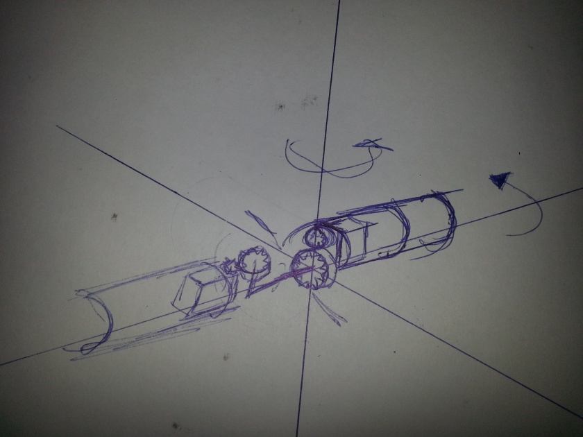
First drawings of the second prototype. The second prototype is focused on creating a joint that makes the structure better resembles a loop and has a integrated gearbox.
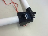
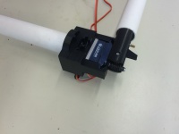
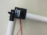
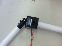
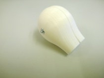
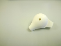
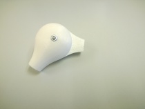
16/3 Prototype 1 (for testing)
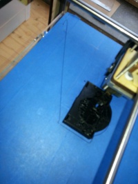
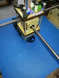
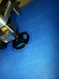
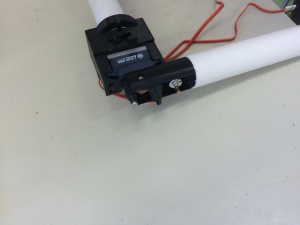
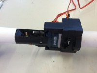
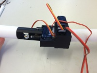
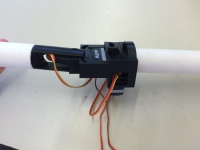
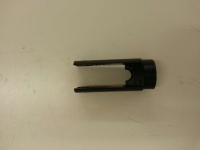
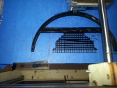
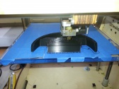
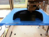
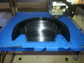
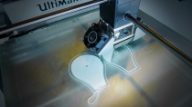
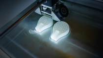
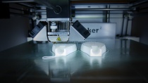
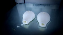
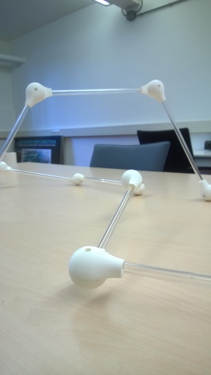
We designed a joint to test the calcultations made. Here are some pictures of the process of 3D printing the joint.
10/3 Calculations
Before designing the joint calculation had to be made to get a idea of the forces working on the structure. The following link will lead to the calculations made in Matlab.
(link deleted)
The Zip file costains 5 files:
- Model_driver_simple.m
- Variables_simple.m
- Calculations_static.m
- Calculations_dynamic.m
- Calculations_strength.m
In Variables_simple.m you change the variables to your design (size, material, weigth, etc.).
When the variable_simple.m file is set to your desired design, you run Model_driver_simple.m. The model will calculate the static torque and dynamic torque needed for that design. It also tells whether the chosen tube (with its properties) is strong enough.
Keep in mind these calculations are made by a bachelor student from mechanical engineering, these are not made by a (offical) professional.
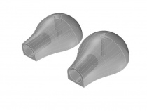
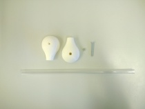
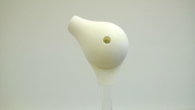
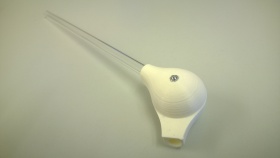
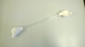
9/3 Joint Design 2 (display version)
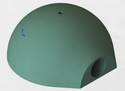
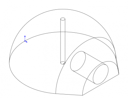
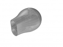
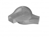
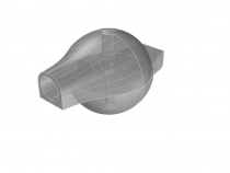
This joint has the shape of the eventual joint, but is oversimplified. These will replace the old joints from de display version of the hyperloop. Per joint 2 of these parts will be printed and a small bolt will hold them together.
Printing Process
Single_Joint_Component
2/3 Decisions Joint Prototype 1
Decisions made about the mechanism, shape and gearbox of prototype 1.
The mechanism
The mechanism will be a hinge + cylindrical movement. This can move the required degrees of freedom, is able to handle great forces and only needs 2 engines.
The shape
The shape will be a combination of the movability and heat dissipation from a sphere and the strong construction of a cylinder.
Gearbox
A gearbox is not yet needed for the first prototype. The design of the gearbox will be heavily depended on the results from testing prototype 1.
Full file: https://www.dropbox.com/s/nq8xhl8pyzf058q/Decisions%20Joint%201.docx?dl=0
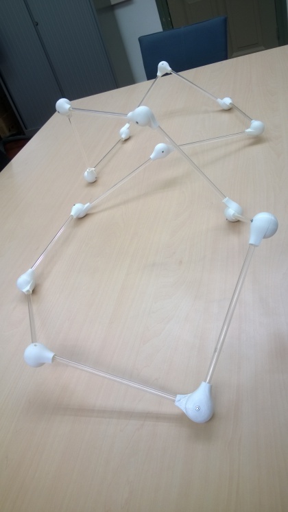
23/2 Joint Design 1
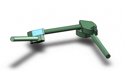
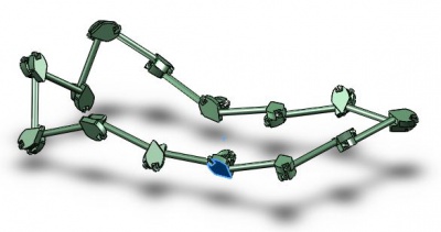
The next 2 figures show the first simple design of the joint and hyperloop that has enough degrees of freedom. This design will be able to rotate and translate. The previous design from architecture could not cope with the rotations. From this point on many aspects have to be changed to meet the criteria, this is just to give an idea of how the joint and hyperloop will be able to move.
